- 您现在的位置:买卖IC网 > Sheet目录2002 > LT8500IUHH#TRPBF (Linear Technology)IC PWM GENERATOR 56-QFN
LT8500
13
8500f
operaTion
A rising edge on the LDI signal is always interpreted as
the end of a frame. The next rising edge of SCKI after the
falling edge of LDIBLANK is always interpreted as the start
of a new frame. An out-of-sync error bit (SYC) is provided
in the status frame to alert the system if the part saw an
LDI unexpectedly. This occurs when LDI and SCKI are
both hi, or when LDI is hi on other than a frame boundary
(n 584 SCKI’s). The SYC bit is for information only, it has
no other effect on the part. If the SYC bit is set, none of
the other data in the status frame is reliable and the effect
of the prior frame is unknown; the LT8500 assumes the
system’s timing of the LDI is correct and considers the
next SCKI as the start of the next frame.
OPENLED
The OPENLED pin provides status information to the
host by reporting its state in the status frame. The state
of the pin is captured by each rising edge of PWMCK and
is reported in two ways. In typical use, the status frame
receives the captured state of the pin on the rising edge
of the first SCKI after LDIBLANK goes low. This state is
duplicated 48 times and reported in the LSB of each PWM
channel in the status frame. The state will normally be a
logic “1” due to the on-chip pull-up resistor.
Alternatively, the LT8500 supports a diagnostic self test
frame (CMD = 0x5X) that reports the OPENLED state
differently. In this case, the LT8500 sequentially pulses
PWM[1] through PWM[48] high for 64 PWMCK cycles
each. The state of the OPENLED pin is captured for each
channel while the corresponding PWM pin is high. This
by-channel data is shifted out in the status frame as the
nextframeisshiftedin.Inaddition,thestatusframewillset
the open LED test bit (OLT), indicating that the OPENLED
data in the current status frame is from the self test. The
statusframewillreturntotypicalreportingonthefollowing
frame. When the LT8500 is used with the LT3595A, the
OPENLED pin and the self test provide a diagnostic routine
to identify the location of open LED faults. See “Diagnostic
InformationFlags”intheApplicationsInformationsection.
OUTPUTS
After power-up or reset, no PWM[48:1] output will turn on
until an output enable frame is sent. The 12-bit PWMCK
counter is free-running from the PWMCK clock when
outputs are enabled. When an output enable frame is sent,
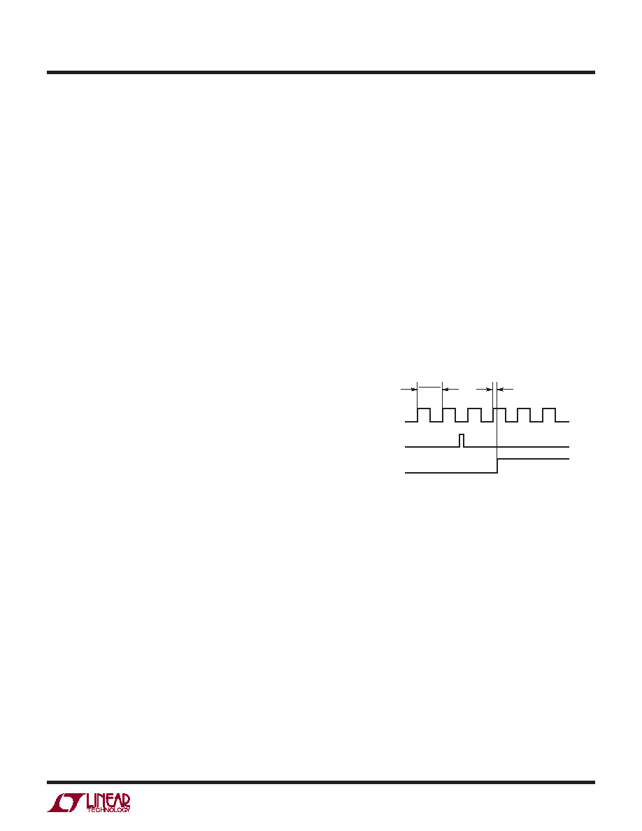
the PWMCK counter increments to one on the second ris-
ing edge of PWMCK after the rising edge of LDIBLANK, as
shown in Figure 5. By default, all outputs with non-zero
values in PWMRSYNC will turn on when the PWMCK
counter is one. Alternatively, if the phase-shift bit (PHS)
is set, the PWM[48:1] outputs will turn on as illustrated in
the phase-shift synchronous updates in Figure 6, case A.
Further discussion of the phase-shift function follows.
Each subsequent rising edge of PWMCK increases the
PWMCK counter by one. Any PWM channel will be turned
off when its PWMRSYNC value is equal to the value in
the PWMCK counter. An output disable frame resets the
PWMCK counter immediately after LDI, and turns off all
the PWM channels on the next rising edge of PWMCK after
LDI. Figure 5 shows the PWM output enable timing chart.
8500 F05
PWMCK
LDI, CMD = 0x30
PWM
1
fPWMCK
0
1
2
3
tPD-PWM
Figure 5. PWM Output Enable Timing Chart
Assumes Outputs Were Previously Disabled
PHASE DIFFERENCE BETWEEN 16-CHANNEL BANKS
By default, the rising edges of all PWM[48:1] channels
occur on the same rising edge of PWMCK. This event
begins a PWM period of 4096 PWMCK cycles. The
LT8500 provides a phase-shift toggle command (CMD =
0x6X) to reduce system noise and current spikes result-
ing from 48 pins switching at once. The function of this
command is illustrated in Figure 6, case A. In phase-shift
mode, the PWM[48:1] outputs are divided into three
16-channel banks that are 120 degrees out-of-phase
with each other within a PWM period. This means that
channels PWM[48:33] will turn on with the rising edge of
PWMCK(1), then channels PWM[32:17] will turn on with
the rising edge of PWMCK(1365), 1/3 of the PWM period,
and channels PWM[16:1] will turn on with the rising edge
of PWMCK(2730), 2/3 of the PWM period.
发布紧急采购,3分钟左右您将得到回复。
相关PDF资料
LTC1096IN8#PBF
IC A/D CONV 8BIT SRL IN/OUT 8DIP
LTC1099ACN#PBF
IC A/D CONV 8BIT HI-SPEED 20-DIP
LTC1197IMS8#PBF
IC ADC 10BIT 500KHZ SHTDWN 8MSOP
LTC1198-1BCS8#PBF
IC ADC 8BIT 750KHZ SAMPL 8-SOIC
LTC1257IS8#TRPBF
IC D/A CONV 12BIT VOLT OUT 8SOIC
LTC1276ACN#PBF
IC A/D CONV 12BIT SAMPLING 24DIP
LTC1278-4IN#PBF
IC A/DCONV SAMPLNG W/SHTDN 24DIP
LTC1279CG#TRPBF
IC A/DCONV SAMPLNG W/SHTDN24SSOP
相关代理商/技术参数
LT-8501M
制造商:Mencom 功能描述:
LT8582EDKD#PBF
功能描述:IC REG MULTI CONFIG ADJ 3A 24DFN RoHS:是 类别:集成电路 (IC) >> PMIC - 稳压器 - DC DC 开关稳压器 系列:- 标准包装:250 系列:- 类型:降压(降压) 输出类型:固定 输出数:1 输出电压:1.2V 输入电压:2.05 V ~ 6 V PWM 型:电压模式 频率 - 开关:2MHz 电流 - 输出:500mA 同步整流器:是 工作温度:-40°C ~ 85°C 安装类型:表面贴装 封装/外壳:6-UFDFN 包装:带卷 (TR) 供应商设备封装:6-SON(1.45x1) 产品目录页面:1032 (CN2011-ZH PDF) 其它名称:296-25628-2
LT8582EDKD#PBF
制造商:Linear Technology 功能描述:DC/DC CONVRTER BOOST INVERTING SEPIC
LT8582EDKD#TRPBF
功能描述:IC REG MULTI CONFIG ADJ 3A 24DFN RoHS:是 类别:集成电路 (IC) >> PMIC - 稳压器 - DC DC 开关稳压器 系列:- 设计资源:Design Support Tool 标准包装:1 系列:- 类型:升压(升压) 输出类型:固定 输出数:1 输出电压:3V 输入电压:0.75 V ~ 2 V PWM 型:- 频率 - 开关:- 电流 - 输出:100mA 同步整流器:是 工作温度:-40°C ~ 85°C 安装类型:表面贴装 封装/外壳:SOT-23-5 细型,TSOT-23-5 包装:剪切带 (CT) 供应商设备封装:TSOT-23-5 其它名称:AS1323-BTTT-30CT
LT8582IDKD#PBF
功能描述:IC REG MULTI CONFIG ADJ 3A 24DFN RoHS:是 类别:集成电路 (IC) >> PMIC - 稳压器 - DC DC 开关稳压器 系列:- 标准包装:250 系列:- 类型:降压(降压) 输出类型:固定 输出数:1 输出电压:1.2V 输入电压:2.05 V ~ 6 V PWM 型:电压模式 频率 - 开关:2MHz 电流 - 输出:500mA 同步整流器:是 工作温度:-40°C ~ 85°C 安装类型:表面贴装 封装/外壳:6-UFDFN 包装:带卷 (TR) 供应商设备封装:6-SON(1.45x1) 产品目录页面:1032 (CN2011-ZH PDF) 其它名称:296-25628-2
LT8582IDKD#PBF
制造商:Linear Technology 功能描述:DC/DC CONVRTER BOOST INVERTING SEPIC
LT8582IDKD#TRPBF
功能描述:IC REG MULTI CONFIG ADJ 3A 24DFN RoHS:是 类别:集成电路 (IC) >> PMIC - 稳压器 - DC DC 开关稳压器 系列:- 设计资源:Design Support Tool 标准包装:1 系列:- 类型:升压(升压) 输出类型:固定 输出数:1 输出电压:3V 输入电压:0.75 V ~ 2 V PWM 型:- 频率 - 开关:- 电流 - 输出:100mA 同步整流器:是 工作温度:-40°C ~ 85°C 安装类型:表面贴装 封装/外壳:SOT-23-5 细型,TSOT-23-5 包装:剪切带 (CT) 供应商设备封装:TSOT-23-5 其它名称:AS1323-BTTT-30CT
LT8584IFE#PBF
制造商:Linear Technology 功能描述:IC BATT CELL BALANCE 16TSSOP 制造商:Linear Technology 功能描述:BATTERY BALANCER, 2.5V-5.3V, TSSOP-16, Supply Voltage Min:2.5V, Supply Voltage M